
Conveyor and MPF Setup Instructions
This website will provide instructions on setting up and installing the MPF (multi purpose feeder) with the CV1242 and CV1860 Conveyors.
Initial Setup
Mounting the MPF to the Conveyor
Mounting the Conveyor Legs
Mounting the Conveyor Extrusion
Mounting the Motor Mount
Mounting the Control Box
Click any of the above links to jump to that section
Mounting the MPF to the Conveyor
Tools Required: T40 Torx Bit driver.
Helpful Tools: Pick or small screwdriver & a 2nd person to help (or height adjust cart)
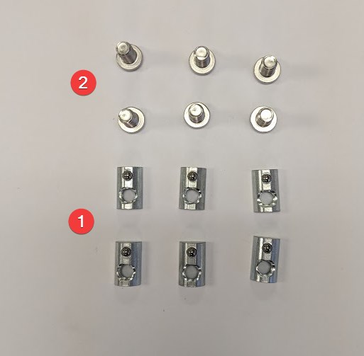
Parts Required:
1. Qty 6 x 1680319 (80/20 - 3921 M6 T-Nut)
2. Qty 6 x 1710082 (M6-1.0 x 12mm Button Head Torx)
1. Identify the different parts of the conveyor in the below diagram. The MPF is designed to install on the infeed of the conveyor while the motor mount is installed on the exit of the conveyor. Note the drive shaft that comes out of the exit driver roller on the back exit of the conveyor.


2. Install 3 x M6 T-nuts into the conveyor channel on the front side of the infeed. T-nuts should be placed 57mm apart between centers. The Holes in the MPF can be used as a guide:


3. Following the instructions in step 2, install the other three remaining M6 - T nuts into the back infeed conveyor channel.

4. After the T-nuts have been inserted, line up the MPF feeder with the bottom lip of the conveyor and install the 6 x M6 screws (with a T40 Torx bit driver) into the T-nuts. A pick or small screwdriver can be useful in lining up the T nut with the holes in the feeder. Keep screws loose.


5. After the 6 x M6 screws have been installed, position the MPF so the top plate is equidistant from the conveyor belt. Ideally, the MPF should be as close as possible to the conveyor without touching as shown below.

6. With the feeder positioned, tighten all 6 x M6 screws. Mounting of the MPF is completed.
Mounting the Conveyor Legs
Tools Required: T40 Torx Bit driver.
Helpful Tools: Pick or small screwdriver
Parts Required:
1. Qty 6 x 1680319 (80/20 - 3921 M6 T-Nut)
2. Qty 6 x 1710082 (M6-1.0 x 12mm Button Head Torx)
3. Conveyor Foot Mount A
4. Conveyor Foot Mount B
5. Qty 2 Spacer Plates


Note that MPF serves as two of the legs needed for a conveyor. If the conveyor is a standalone system without the MPF, 2 sets of each leg are required and can be installed on the infeed of the conveyor.

MPF mounted on CV1860

Table top feed mounted on CV1242
This guide will be for the Front Exit Foot Install - use the above picture to determine the foot direction and spacer direction for other feet installations.
1. Install 3 x M6 T-nuts into the conveyor channel on the front side of the conveyor exit. The spacer plate can be used as a guide.


2. Place the spacer plate on the bottom lip of the conveyor and line up the T-nuts with the holes

3. Line up the Front conveyor mount with the spacer plate and using a T-40 bit driver install the 3 x M6 screws into the T nuts. Leave Loose.


4. Slide foot assembly to the desired location on the conveyor and tighten the 3 x M6 Screws with T-40 Bit driver
Mounting Conveyor Extrusion
Tools Required: 5mm hex driver.
Helpful Tools: Pick or small screwdriver
Parts Required:
1. Qty 2 x 1680319 (80/20 - 3921 M6 T-Nut)
2. Qty 2 x 1680185 (M6-1.0 x 35 SHCS)
3. Qty 1 x 1690089 (360mm Aluminum Extrusion (4040) - Drilled and Tapped)


1. Extrusion will be installed in the near the middle front of the conveyor. Install Two T-nuts into the front conveyor channel using the extrusion holes as a guide.

2. Line up holes with extrusion and insert 2 x M6 x 35 Socket head cap screws using 5mm Hex Driver - keep loose.

3. After both screws have been installed, line up the extrusion so it is flush with the top of conveyor. Tighten M6 screws using 5mm hex driver

NOTE: Depending on extrusion mounting location, It may be necessary to move the bottom belt tensioner shown below. It can be moved by loosening the two screws using a 4mm hex driver and slid out of the way of the extrusion.

Mounting the Conveyor Motor and Motor Mount
Tools Required: 2mm hex driver, 3mm Hex Driver, 4mm Hex Driver, 13mm wrench, T20 Torx Bit, T30 Torx Bit Small rubber mallet
Parts Required:
1. Qty 1 x 1690032 (12mm ID 16 Tooth XL Pulley)
2. Qty 1 x 1690033 (18mm ID 21 Tooth XL Pulley)
3. Qty 1 x 1690014 (Belt Guard)
4. Qty 3 x 1710080 (M4-0.7 x 8mm Button Head Torx)
5. Qty 3 x 1710094 (M6-1.0 x 20mm Button Head Torx)
6. 120W motor Mounted
7. 90XL037 Timing Belt


1. Using a 4mm Hex driver, remove the three black M6 screws securing the belt tensioning mechanism on the back side exit of the conveyor - these screws will no longer be used.

2. Place the motor mount so that the motor sits under the conveyor. Using a T30 Torx driver, secure the motor mount with 3 x M6 x 20 screws using the same hole locations in step 1.

3. Install the 12mm ID 16 Tooth XL Pulley onto the conveyor drive shaft ensuring the key lines up with the keyhole. Note that this is a tight fit and a mallet may be required. Pulley should be installed flush with the conveyor. Once in position, tighten the two set screws using a 2mm hex driver.


4. Install the 18mm ID 21 Tooth XL Pulley onto the motor ensuring that the keyway lines up with the key. It may be necessary to back off the set screws in the pulley with a 3mm hex driver before installing. After installing the pulley onto the shaft, position it so it is centered with the conveyor pulley. Once positioned correctly, tighten both set screws using 3mm hex driver.


5. Loosen the 4 x M8 screws using a 13mm Wrench so the motor mount can move freely in the slots.

6. Ensure that the motor is in its up most position (closest to conveyor belt) and roll on the 90XL037 Timing Belt. One the timing belt is on both pulleys, tension the motor downwards until belt is taught. Tighten the 4 M8 nuts using a 13mm wrench.


7. Install Belt guard onto standoffs using a T20 torx driver and the provided 3 x M4 x 8 screws.


Note - the extra hole in the motor mount can be used with a TR1 Encoder.
Mounting the Control Box
Tools Required: T40 Torx Driver
Parts Required:
1. Qty 2 x 1710097 (M8-1.25 x 25mm Button Head Torx )
Note that the control box mounts onto the Conveyor extrusion and contains the motor drivers for the conveyor and the feeder.
1. Line up the control box with the conveyor extrusion.

2. Using a T-40 torx driver, install the two M8 screws through the bracket and into the extrusion. One screw installs on each side

3. Locate the cable from the back of the control box. The cable farthest to the right will always be the conveyor driver. If the control box is equipped with a feeder controller, it will be in the second poistion.

4. Connect the conveyor cable and feeder motor cables to each respective motor.


