
PM-417 Print Head Replacement
Supplement from Service Manual (PDF)
Note: Before starting printhead replacement, ensure that ink levels are at least 30% full or higher and that the maintenance cartridge (if used) is less than 50% full.
1. Open the maintenance utility, select Key Operator Mode (default) and press okay

2. Select USB as Connecting port (default) and press okay

3. Navigate to the Parts Replacement Tab at the top of the maintenance Utility


4. Select the parts to be replaced. In this case we will only be changing the printhead assembly so we select "Printhead" and then click Start

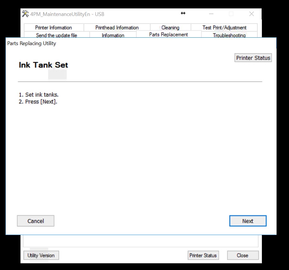
5. A Parts Replacement Utility will appear. Press Next to restart the printer into a maintenance mode

6. After the printhead has restarted, the Parts replacement utility will prompt you to drain the ink from the installed head. Click next to start this process.

7. Ink will begin to drain from the printhead. The first half of this process takes about 6-7 Minutes.

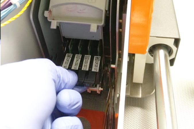
8. After step 1 has completed, the Parts Replacing Utility will now prompt you to remove the ink tanks.

Remove the Black, Cyan, Magenta, and yellow ink tanks from the printer by unlatch the blue latches and pulling out each cartridge leaving the blue latches open

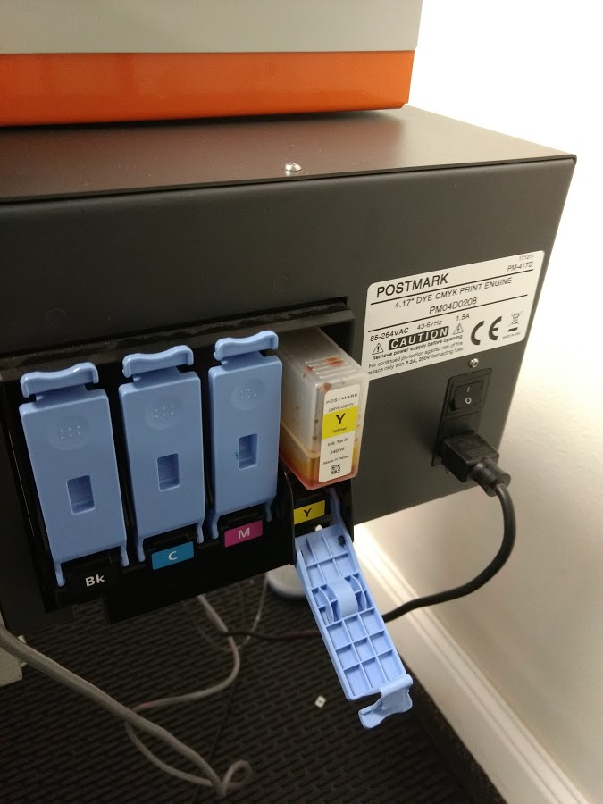
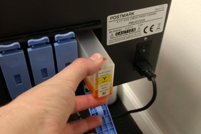

Once all four cartridges have been removed, press OK in the utility to continue draining ink from the system.
9. The system will continue step two of the ink draining process. This step takes approximately 10 minutes.

10. Once the system has finished, the Parts Replacing Utility will prompt you to turn off the power to the system.

Turn off the main power (above where the power cord plugs in next to the ink tanks) and press next in the utility

11. The utility will now show some diagrams on removing the printhead and blade cleaner, but there are a few things we must do before we can access these parts. First, raise the printhead by turning the height adjustment knob clockwise so it is its maximum position.

If the knob gets too hard to turn do not over tighten as it may stirp out the gear assembly. The printhead should be roughly 1/2 - 3/4" off the transport surface (12-19mm) as shown below:

12. Loosen the printhead slide knob and move the printhead to its outer position away from the ink tank box. Note if you feel something snagging during this stop pulling as the ink lines or wiring assembly may be caught.

Once it has been moved, tighten the adjustment knob to lock the printhead in place
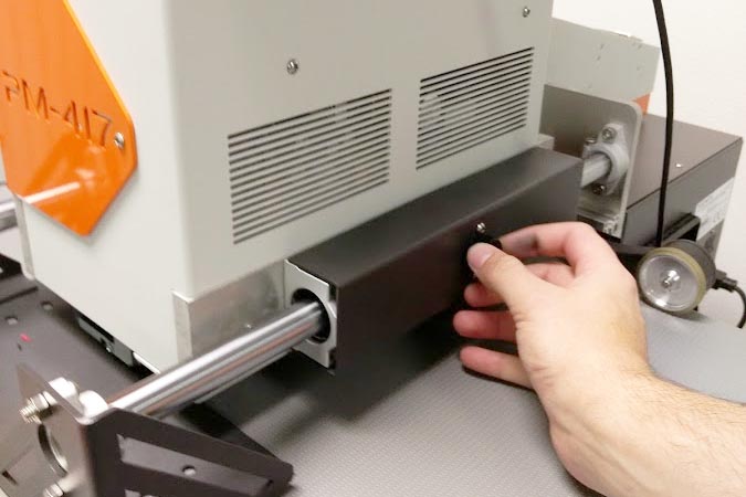
13. Remove the back channel cover by firmly pulling up

14. While not necessary, it sometimes help to remove the the two forward brackets for more room to work with using a T-10 Torx driver.


14. At this point it recommended to use included gloves. Move wire assembly and ink lines off to the sides so that there is a clear channel for the printhead to be removed.

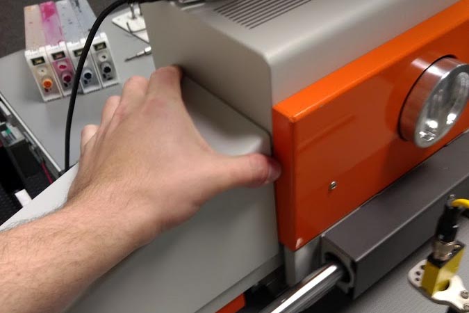
15. Remove protective cover from internal module by pulling out from the top tab


16. We are now ready to remove the printhead and blade cleaner. It is recommended to have a paper towel or bin to place these objects after removal. Lift up on the handle marked "1" on the print module - reference the diagrams shown in the parts replacement utility for further reference


17. Next push down on the handle marked "2" - again use the on screen diagrams in the parts replacement screen for further reference. The clip should spring open downwards exposing the blade cleaner


18. Next remove the blade cleaner which sits below the printhead (marked YMCK)

Set aside blade cleaner for reinstallation after printhead replacement

19. Next, remove printhead from module by pulling on the handle marked YMCK firmly back towards the back of the PM-417.
Note: it is important not to touch the bottom of the printhead where the nozzles are as they can easily be damaged.

Set used printhead on its side on a paper towel in order not to damage the nozzles (if it is to be reused or sent in or diagnoses)

20. Unbox and dock the replacement printhead and prepare to install reverse of installation.
NOTE: Be very careful not to touch the bottom of the printhead where the nozzles are as they can be easily damaged.

21. There are two pins on the sides of the printheads that need to line up with two channels in the module. Bring the print head into position and slide it towards the front of the PM-417. Once in give it a push until a firm seat is felt


22. Once blade cleaner is seated, install the blade cleaner. The blade cleaner needs to be installed in the following orientation:


23. Once the blade cleaner and printhead have been installed, lift the lower lach "2" back into position until it clicks in to place


24. Once latch 2 has been lifted, push down latch number 1 to seat the printhead connection points - ensure it is firmly down.

25. Using the used docking station from the new printhead, safely dock the old printhead for later use or analysis and reinstall protective cover back into unit


26. Reinstall Back cover on to printer

27. Press Next on the Parts Replacing Utility.
28. Reinstall the ink tanks into their respective locations and press next in the parts replacement utility.
29. Turn the power on to the printhead

30. After powering on the printer, press next in the parts replacement utility to restart the printer out of maintenance mode. The printer will begin to load ink - this process takes approximately 25 minutes. Note it is important that there is at least 20% ink in the cartridge for this process to finish.
After ink has been loaded, the printhead can be returned to its normal height and position and parts replacement has been complete.
For further information and details on this process, please reference the service manual at the following download link:
Also, for more detail on the removal process of the blade cleaner and printhead see the following reference video of an older model printer: