
PM-417 Installation Guide
This website will provide software and information on setting up a Postmark PM-417. This guide is for printers manufactured after July 1st, 2018 (REV B1 Specification).
For Rev A Instructions, please visit our archive
Helpful Links to Get started:
Mounting Instructions for Postmark 12" and 18" Conveyor (PDF)
Xitron Software installation and Setup (link)
Maintenance Utility Download (zip)
Canon Service Manual for Print Engine (PDF)
Initial Setup
After mounting your PM-417 to your transport system there are a few connections that need to be made prior to turning on the system.
Encoder
TOF Sensor
Ink Lines
Computer Connections
Turning on the System
Click any of the above links to scroll to that section
Encoder
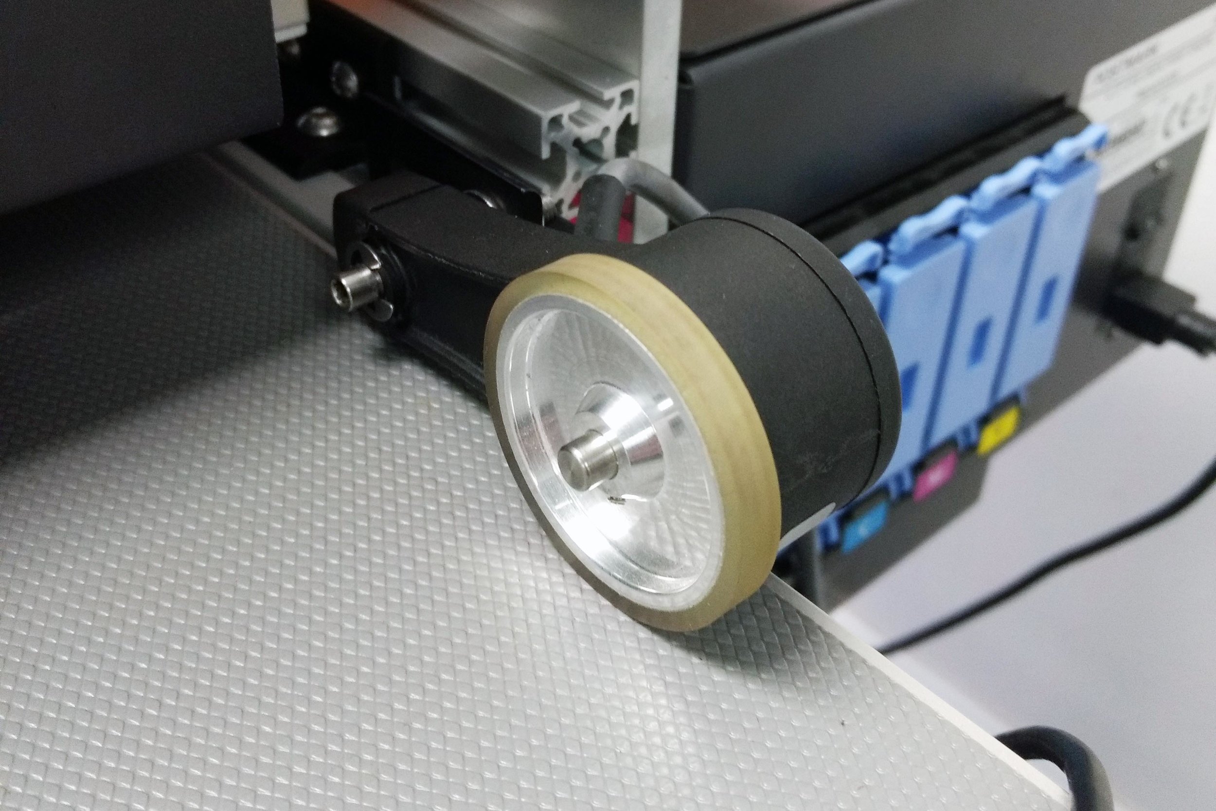
Figure 1: 1800 pulse per revolution encoder with a 6" circumference wheel
The encoder provides the speed of the transport belt to the printer to ensure accurate registration and stitching. The PM-417 requires a 300PPI input. All postmark provided encoders use an 1800 pulse per revolution encoder with a 6" circumference wheel (Figure 1). The input connector for the encoder is an M12 Circular connector (Figure 2). After securely mounting the encoder using the included instructions, connect the M12 cable from the encoder to the input box (Figure 3).

Figure 2: M12 connector on the end of the encoder cable

Figure 3: Connection point for encoder on input box
Photo Sensor (TOF - Top of Form Sensor)

Figure 4: Contrast TOF sensor
The Photo Sensor (also referred to as TOF sensor) identifies the leading edge of the substrate being printed on. Different substrates and transport assemblies may require different types of TOF sensors. The postmark provided sensor is a contrast sensor which can be used with a retroreflective target or on a solid belt (Figure 4). The input connector on the Ink Tank Assembly Box for the sensor is a 4pin M8 circular connector. This connection is common for most industrial sensors.
The included mounting hardware for the sensor can be used for standard 22mm sensor mounts as well as a variety of fiber optic cable sensors for specific applications.
Using a T30 Torx bit, install the rail onto the back plate of the system as shown below:


To install the sensor, loosen the orange handle and slide the sensor mount onto the 12mm shaft (Figure 5).
Center the sensor where media will be fed and lock the sensor in position (Figure 6).
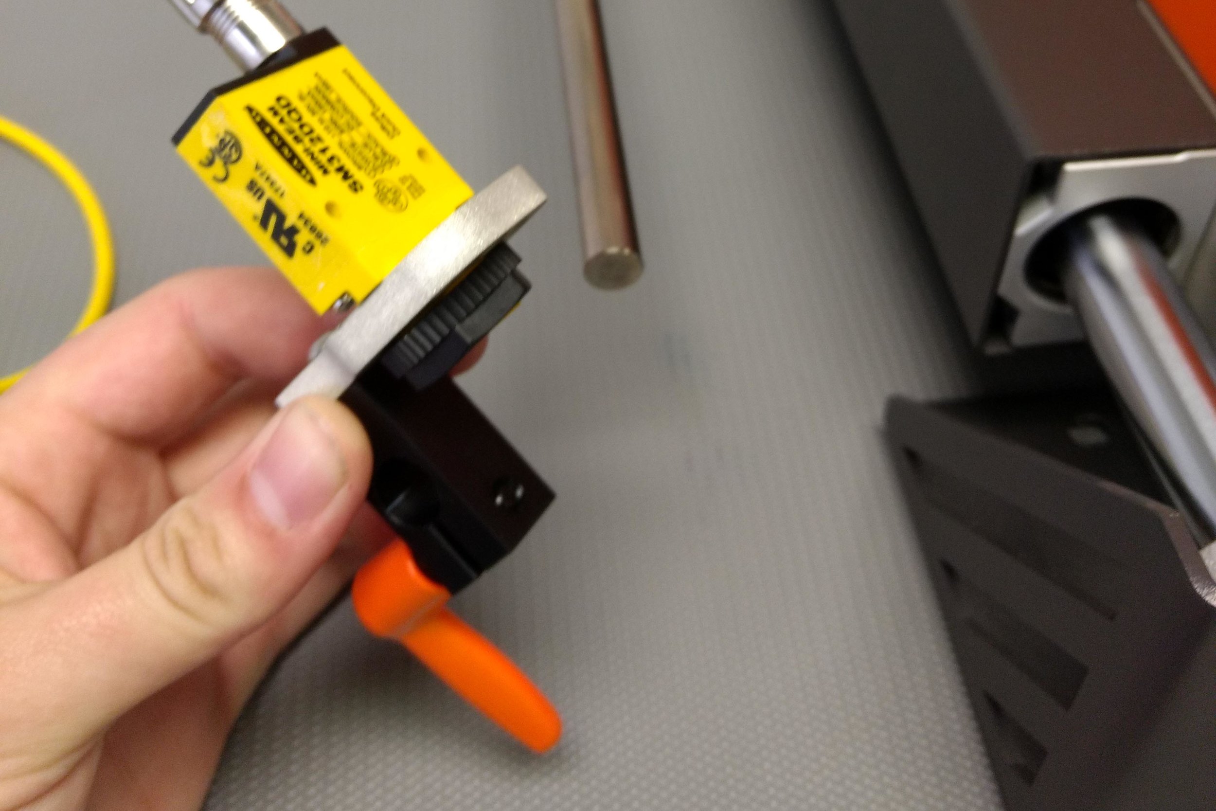
Figure 5: Loosen the orange handle and slide the sensor mount onto the 12mm Shaft

Figure 6: Center the sensor where media will be fed and lock the sensor in position
After the sensor has been mounted, connect the M8 connector from the sensor's yellow cord (Figure 7) to the back of the input box next to the encoder input (Figure 8).

Figure 7: M8 Plug at the end of the yellow cable that connects to the sensor

Figure 8: Plug location on Ink Tank box for Sensor input
Connecting Ink Lines
Third generation PM-417 printers are equipped with quick disconnect fittings which allow for bulk ink connection. Each system will come with the following ink line connectors which are described below
Ink Line Kit

The ink line kit connects bulk ink (bags or system) to the PM-417.
Waste Ink Kit

The waste ink kit includes a 36" line and a 128oz (3.75L) container for waste ink. It is very important that the waste ink line is connected at all times when using the system. Other containers can be used for waste ink as long as they are not pressurized
Cap Kit

The Cap Kit can be used to cap connections when they are not in use such as shipping or when ink is draining for printhead replacements.
Drain Kit

The drain kit consist of four ink lines and quick disconnect fittings. These lines are used when draining the system of ink for shipping or for printhead replacements.
Start by removing the caps from the input box by rotating them 90° and pulling. Note there may be ink inside these fittings - the use of gloves is advised when connecting or disconnecting ink lines.


If using bagged ink, install the bags onto the bag hook as shown below

Connect each bag to the appropriate ink inlet by pushing on the connector and turning 90° to lock it into place


Once all 4 ink lines have been installed into the input box, connect the other end of the ink line to the corresponding bag of ink by pushing in the connector and turning 90° to lock into place.
Ensure that the color of the bag lines up with the input channel which is shown below:


Connect the waste connector and route to a waste container.


Computer Connections
In order for a computer to communicate with the PM-417, a USB and a serial RS-232 connection are required. Postmark includes a 6ft USB A to B Cable which installs on the back side of the Ink Tank Assembly Box near the encoder and photocell input.
1. USB
USB is the main connection that drives the printhead. All print data, service instructions, and settings are sent via USB. The USB connection port is shown in Figure 10.
The maintenance utility will only communicate over USB.
2. RS-232
RS-232 provides the necessary "start print" and "stop print" commands required by the printhead to print. These communications are handled either by the Xitron software or by an external controller. Without the RS-232 communication, the printer will never start printing although it may show the status as "printing".
Postmark includes a USB to RS-232 adapter (Figure 11) which allows this communication to be sent via an emulated serial port in windows.
Drivers for the USB to Serial converter and information on serial protocol can be downloaded here:

Figure 10 : USB connection on Ink Tank Assembly Box

Figure 11: Serial commuincation port with USB to RS-232 adapter
Starting the printer for the first time
The printer should start loading ink automatically as long as everything is connected correctly and there are no errors. It is recommended to watch the printer status during this process by opening the maintenance utility.
If you are getting ink tank errors upon turning on the system, ensure that the chip activation light is illuminated green. If it is illuminated red, press it to toggle the chip activation and power cycle the printer:

Using the Maintenance Utility
Download the maintenance utility .zip file from the link below and extract the contents to a known location:
A 64 bit operating system is recommended for most applications including use of the Maestro / Xitron software. The 64 bit version of the maintenance utility can be found in the 64 bit folder included in the above link.
The maintenance utility is a self sufficient program and does not require an installer. You will just need to open the correct version based on your operating system.
With the printer turned on and connected, run the maintenance utility 4PM_MaintenceUtilityEn.exe
A window will come up prompting a mode to be selected (Figure 13).

Figure 13: Maintenance Utility mode selection
For most applications, key operator mode is sufficient.
For advanced servicing and troubleshooting, Administrator Mode can be used by inputting the password: printmodule
For the initial setup run the maintenance utility in "key operator mode".
Next a window will come up asking which connection the printer is using (Figure 14), in most cases this will be via USB. The maintenance utility can be ran in offline mode for training or remote servicing aid.

Figure 14: Connection port selection
The maintenance utility will now be ready to use given the printer is working correctly. The following manual can be referenced for details on the functionality of the maintenance utility:
PM-417 Maintenance Utility Manual
As the printer is loading ink, press the printer status button in the maintenance utility to monitor the status (Figure 15).

Figure 15: Printer Status button in the maintenance utility window
The ink loading process usually takes about 30 minutes. If any error codes arise during this process consult the service manual for more details. If ink does not start loading it is possible there is an error preventing the printer from starting, which will be shown in the printer status window. Again, consult the service manual if this happens.
Once the ink has finished loading the status of the printer should show online / ready (Figure 16):

Figure 16: Printer Status - Online / Ready
At this point setup has been completed and you are ready to install the xitron software as explained here:
Xitron Software Installation Guide
Please note that a sample print from the Xitron software must be made before you are able to print test patterns and calibrations from the maintenance utility, doing so initializes the RS-232 serial communication. The Xitron software handles the RS-232 communication and must be open (unless you are using an external controller).