
PM-417 Purge Unit Replacement
Supplement from Service Manual (PDF)
1. Open the maintenance utility, select Key Operator Mode (default) and press okay

2. Select USB as Connecting port (default) and press okay

3. Navigate to the Parts Replacement Tab at the top of the maintenance Utility


4. Mark the Purge Unit check box and press Start

5. A Parts Replacement Utility will appear. Press Next to restart the printer into a maintenance mode

6. The Parts Replacing Utility will prompt you to turn off the power to the system.

Turn off the main power (above where the power cord plugs in next to the ink tanks) and press next in the utility

7. The utility will now show some diagrams on removing the printhead and blade cleaner, but there are a few things that need to be done before the parts can be accessed . First, raise the printhead by turning the height adjustment knob clockwise so it is its maximum position.

If the knob gets too hard to turn do not over tighten as it may strip out the gear assembly. The printhead should be roughly 1/2 - 3/4" off the transport surface (12-19mm) as shown below:

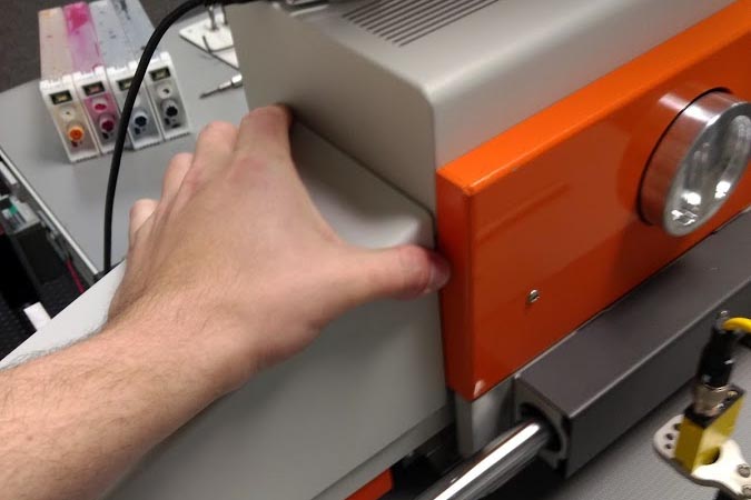
8. Loosen the printhead slide knob and move the printhead to its outer position away from the ink tank box. Note if you feel something snagging during this stop pulling as the ink lines or wiring assembly may be caught.

Once it has been moved, tighten the adjustment knob to lock the printhead in place
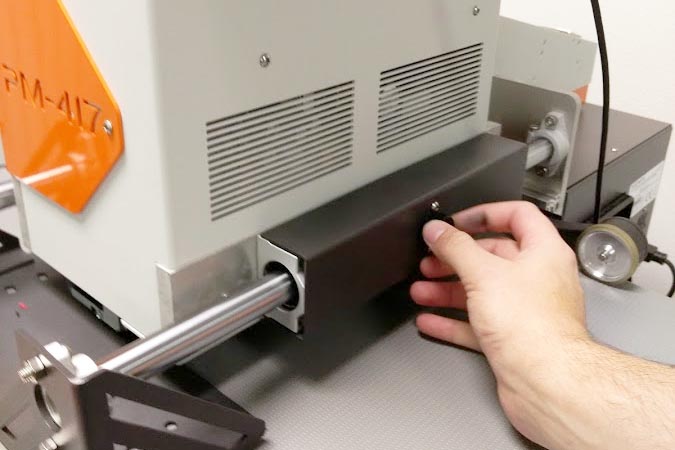
9. Remove the back channel cover by firmly pulling up

10. While not necessary, it sometimes help to remove the the two forward brackets for more room to work with using a T-10 Torx driver.


11. At this point it recommended to use included gloves. Move wire assembly and ink lines off to the sides so that there is a clear channel for the purge unit to be removed.

12. Follow the onscreen instructions to remove protective cover from internal module by pulling out from the top tab


13. Locate the gray tab on the installed purge unit and pull it back. It should hinge towards the left as shown below:


14. Slide Purge unit out the back of the printer - be sure to keep the purge unit level as there may be residual ink left in the purge unit.

15. Make note of the Wipe position value on the side of the new purge unit

16. Install the new purge unit into the printer. Push back the purge unit lightly (it has springs installed in the back and secure the grey clip to lock it in place. Ensure it is locked in place by trying to pull on it.


17. Reinstall Plastic Cover on Print Module

18. There is a label on the print module which shows values for Wipe_P, Print_P, and Cap_P. Make note of the value for Cap_P


18. Reinstall Back cover on to printer

19. Press Next on the Parts Replacing Utility.

20. When prompted, turn on the main power.


21.Enter the Purge Unit Wipe Position which was taken from the side of the replacement purge unit. Once the value has been entered, click next.


22. Press Next to restart the printer

23. Parts replacment has been complete. Press complete to close the parts replacement utility.

Verification of Printhead Cap Position
The Printhead Cap position value is a value that ensures that the printhead is making a proper seal on the purge unit. The printhead cap position can be verified in the administrator mode of the maintenance utility. This value is displayed on the print module as shown below:

Note, the Head Print Position should never be copied from the module sticker - this value is set specific to the outer hardware of the printer.
Open the maintenance utility as an administrator using the password "printmodule"
Once open, navigate to the Test Print / Adjustment tab and click the button "Print Module setup"

A Print Module Setup window will appear. Click the button Read from printer to show stored values.

Verify that the Head Cap Position matches the value printed on the print module.
f a change is made to the head print position, press the button send and save to printer.
