
CP Conveyor Setup Instructions
This website will provide instructions on setting up and installing the CP Frame and CV1860 Conveyors
Start by loosening the M6 Screws circled below with a T30 Torx Driver. This will allow the front conveyor mount to slide:
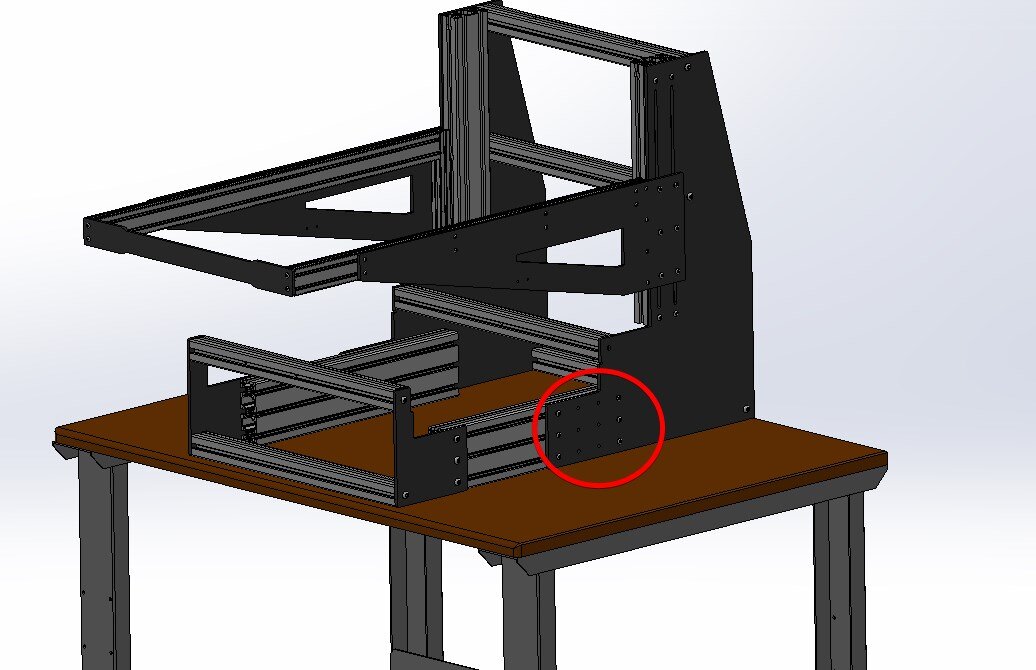

Slide out the front half of the CP Frame roughly 2” wider than the conveyor being mounted. Place the conveyor into the frame and line up the notches on the back side of the CP frame with the back of the conveyor

Once the back side has been inserted into the notch, lift up the front side of the conveyor and slide in the front half of the CP frame so that the lower part of the conveyor lines up with the notch on the CP frame. The M6 screws loosened earlier can now be tightened and the conveyor should be mounted securely.

Mounting the Conveyor Motor and Motor Mount
Tools Required: 2mm hex driver, 3mm Hex Driver, 4mm Hex Driver, 13mm wrench, T20 Torx Bit, T30 Torx Bit Small rubber mallet
Parts Required:
1. Qty 1 x 1690032 (12mm ID 16 Tooth XL Pulley)
2. Qty 1 x 1690033 (18mm ID 21 Tooth XL Pulley)
3. Qty 1 x 1690014 (Belt Guard)
4. Qty 3 x 1710080 (M4-0.7 x 8mm Button Head Torx)
5. Qty 3 x 1710094 (M6-1.0 x 20mm Button Head Torx)
6. 120W motor Mounted
7. 90XL037 Timing Belt

1. Using a 4mm Hex driver, remove the three black M6 screws securing the belt tensioning mechanism on the back side exit of the conveyor - these screws will no longer be used.

2. Place the motor mount so that the motor sits under the conveyor. Using a T30 Torx driver, secure the motor mount with 3 x M6 x 20 screws using the same hole locations in step 1.

3. Install the 12mm ID 16 Tooth XL Pulley onto the conveyor drive shaft ensuring the key lines up with the keyhole. Note that this is a tight fit and a mallet may be required. Pulley should be installed flush with the conveyor. Once in position, tighten the two set screws using a 2mm hex driver.


4. Install the 18mm ID 21 Tooth XL Pulley onto the motor ensuring that the keyway lines up with the key. It may be necessary to back off the set screws in the pulley with a 3mm hex driver before installing. After installing the pulley onto the shaft, position it so it is centered with the conveyor pulley. Once positioned correctly, tighten both set screws using 3mm hex driver.


5. Loosen the 4 x M8 screws using a 13mm Wrench so the motor mount can move freely in the slots.

6. Ensure that the motor is in its up most position (closest to conveyor belt) and roll on the 90XL037 Timing Belt. One the timing belt is on both pulleys, tension the motor downwards until belt is taught. Tighten the 4 M8 nuts using a 13mm wrench.


7. Install Belt guard onto standoffs using a T20 torx driver and the provided 3 x M4 x 8 screws.


Note - the extra hole in the motor mount can be used with a TR1 Encoder.
Mounting the Motor Control Box:
The control box can be mounted in various positions along the conveyor. Postmark’s recommended mounting location is shown below:

The motor control box attaches using 2 x M6 x 12mm Screws and roll in T-nuts that slide into the extrusion channel

After the Motor controller has been mounted, connect the motor controller cable to the motor:


At this point the 1170 Printhead can be placed into the frame - please see 1170 setup instructions before proceeding to this step as there are some shipping brackets that need to be removed:

Included are two lock knobs that install as shown below:


Next install is the cross bar on the outer extrusion.
This installs as shown below using 4 x M5 Screws (T25 Torx)

Using an M6 T-nut, install the photo sensor arm to the conveyor. It is recommended to install this as close to the printhead as possible

After it is installed, slide the photo sensor onto the bar:

Setup of the CP Base should now be complete.